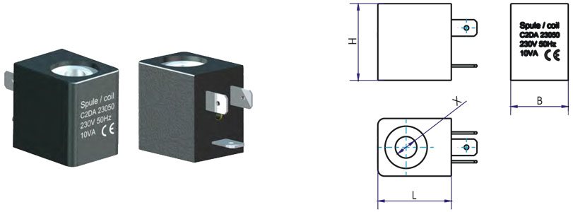
| ambient temperature |
-5°C to +50°C, higher allowed ambient temperatures on request |
| fluid temperature |
see specifications of the particular coil |
| material |
winding copper, temperature class H (180°C), magnetic plate steel zinc plated, encapsulation material see specifications of the particular type |
| standard voltage |
24V DC, 24V 50Hz, 230V 50Hz |
| special voltage on request |
6 – 200V DC, 12 – 250V AC, please note – minimum quantities |
| general duty cycle |
100% ED (DB), continuous operation unless stated otherwise |
| acceptable voltage tolerance |
+/- 10% according to VDE0175 (DIN EC 60038) |
| special duty cycle |
For coils with duty cycle < 100% ED the maximum duty cycle time is 2 minutes for system 5,7 and 9, and 3 minutes for system 13,16 und 19 according to VDE 0580 |
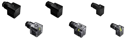
| protection class |
IP65 according DIN EN 60529 (DIN 40050) only with correctly mounted connector and profile seal |
| special version |
please note – minimum quantities must be ordered for special types |