Solenoid valves are actuators used to control pressurized media. They are actuated by switching on the solenoid coil of the valve, whereupon the valve opens (Normally Closed, NC) or closes (Normally Open, NO). A solenoid valve closes when the so-called seat seal closes the valve seat. The solenoid valve can be actuated in three ways:
- Direct-operated
- Pilot operated (pilot controlled)
- Forced-acting (semi-direct-acting)
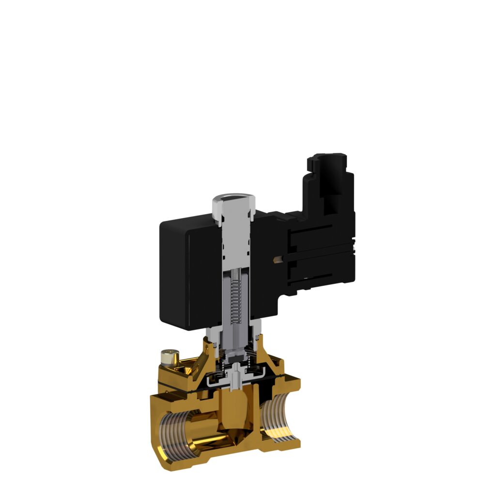
The four central elements of a solenoid valve are:
- the valve body, consisting of at least 2 ports (outlet and inlet) and a valve seat to close the valve.
- the guide tube to hold the solenoid coil and the solenoid core, which together with the pole in the guide tube close the magnetic circuit. In the case of AC voltage supplies, it is necessary for the pole to be equipped with a so-called short-circuit ring.
- the magnetic core, which is freely movable in the guide tube and serves to seal the valve seat or pilot bore.
- the coil, which generates an electromagnetic field by which the core is attracted to the pole.
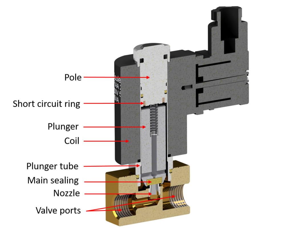
The valve body – has 2 or 3 ports to make the connection to the rest of the pneumatic or hydraulic circuit. Depending on the application and medium, the valve body is usually made of plastic, brass, aluminum or stainless steel (colloquially and hereinafter referred to as stainless steel).
Guide tube, solenoid core and pole – are made entirely or partially of magnetizable stainless steels to create a magnetic circuit. The use and selection of the magnetic stainless steel influences the achievable electromagnetic force of the magnetic system and the corrosion resistance of the valve.
The valve seat – or its nozzle diameter (commonly referred to as nominal size) – influences the achievable flow rate of the valve. The larger the nominal size, the greater the achievable flow rate at a given pressure. Furthermore, the nominal size influences the switchable pressure of direct operated valves. The differential pressure from valve inlet to valve outlet multiplied by the area of the valve seat determines the force required to actuate the solenoid core, which the solenoid coil must apply to lift the solenoid core from the valve seat.
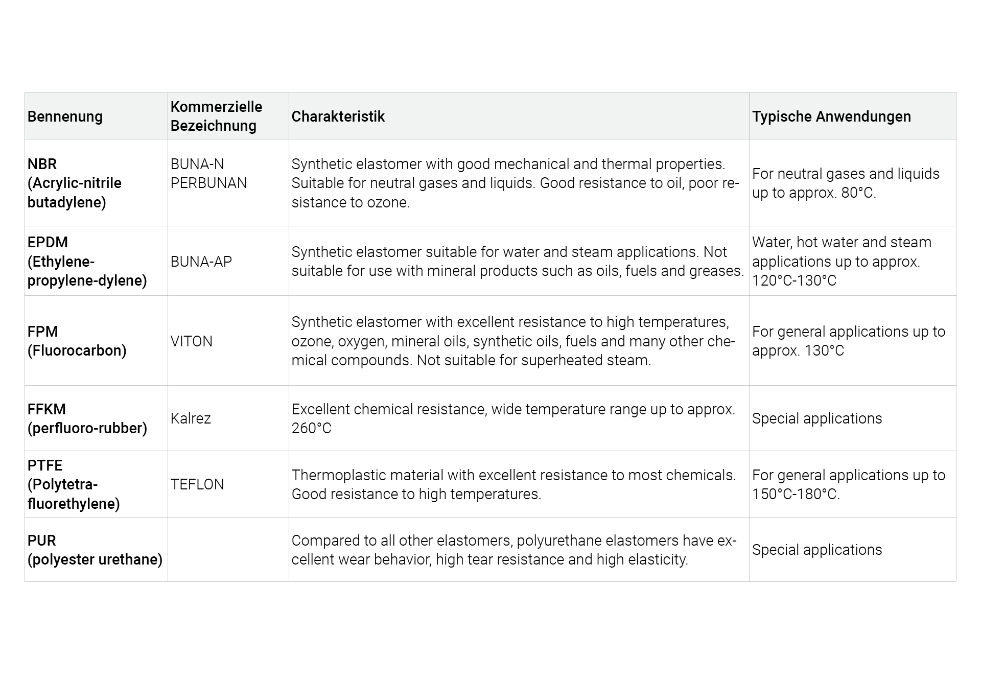
The seal – of the valve seat and the seals used in the valve determine with which media and at which temperatures the valve can be used. The hardness of the seat seal used also influences the abrasion resistance and the leakage rate.
The solenoid coil – serves as an energy converter from electrical energy to mechanical energy. The solenoid coil must be adapted to the existing electrical power supply (e.g. 230V 50Hz or 24Vdc) when designing the valve. The higher the power, i.e. the product of current through the coil and its number of turns, the higher the available mechanical force and thus the switchable pressure difference.
The short-circuit ring – is necessary when valves are operated on AC voltages. Due to the sinusoidal voltage supply, there are zeros both in the voltage curve and in the curve of the generated electromagnetic force of the solenoid system. To prevent the solenoid core from falling off at the zero points of the force curve, a short-circuit ring made of copper or silver is pressed into the solenoid pole. This prevents zeros of the electromagnetic force from occurring on the magnetic core and the latter from starting to oscillate, which causes a characteristic, loud 100 Hz hum.
The circuit diagram of a solenoid valve shows the type of actuation and reset of the valve as well as the switching positions that can be assumed. The following illustrations show this using a directly controlled 2/2-way NC solenoid valve.
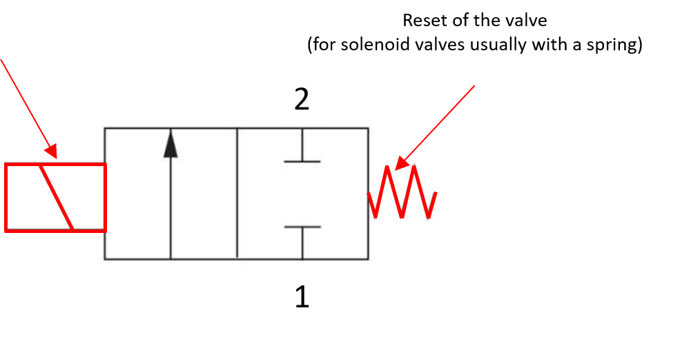
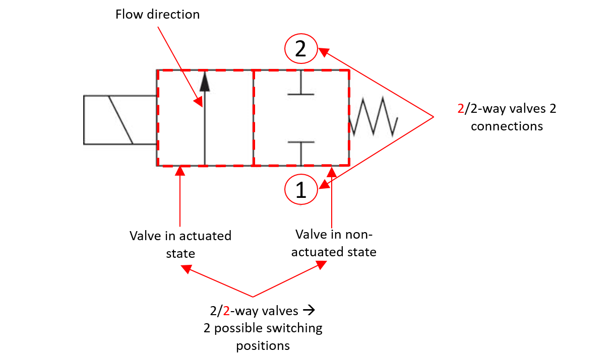
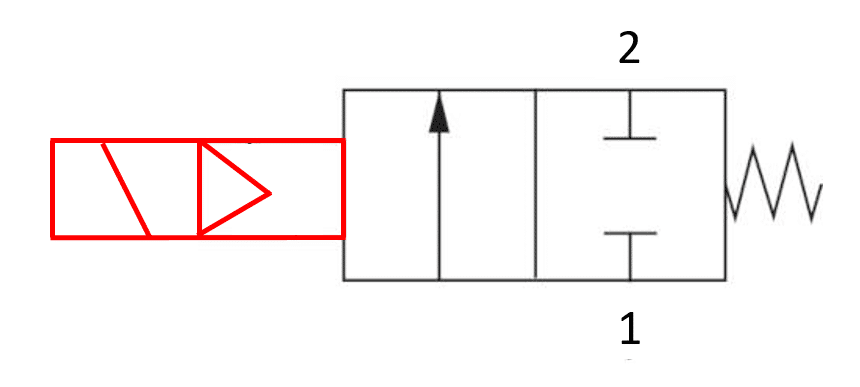
In pilot-operated and positively controlled solenoid valves, the seat seal is no longer actuated purely by the electromagnetic force, but also by the force from the pressure difference between the inlet pressure and the outlet pressure. For pilot-operated or force-operated valves, the switching symbol is therefore adapted to indicate this.
The valve body of 2/2-way solenoid valves has an inlet and an outlet which are connected to each other via a valve seat. Depending on the design, the solenoid valve assumes the position “Normally Closed” (NC) or “Normally Open” (NO) in the non-activated state. An NC solenoid valve locks the valve seat when the solenoid is not energized, preventing flow from inlet to outlet. When the solenoid is energized, the seat seal opens the valve seat and flow is possible from the inlet to the outlet. In a NO solenoid valve, a medium can flow from the inlet to the outlet when the solenoid coil is in the non-actuated state. If the solenoid coil is switched on, the seat seal blocks the valve seat and flow from the inlet to the outlet is interrupted.
For SVS, the identification for an NC or an NO valve is made on the basis of the third digit or the first letter in the product key. The letter A stands for the NC function, the letter B for the NO function. This means, for example, for a valve type 15 NO: 15B-1B20FZ-AC2DA 23050
In a direct operated valve, the armature with the seat seal is actuated purely by the electromagnetic force of the solenoid coil. The rule for NC valves is that the higher the pressure and the larger the nominal size of the valve, the more force is required to actuate the solenoid core. In NO valves, the electromagnetic force works against the spring force of the spring, which pushes the seal carrier of the seat seal away from the valve seat. In order to close the valve, the electromagnetically generated force must therefore be greater than the spring force. The maximum pressure at which the valve still opens is determined by the spring.

At SVS, type series 12, 15, 20, 21, 27 made of brass and type series 31, 32, 34, 35 and 37 made of stainless steel are available as direct operated 2/2-way solenoid valves.
Due to the high demand for electromagnetic force, directly controlled solenoid valves are not suitable for switching large nominal sizes and/or large pressure differences. To reduce the required electromagnetic force and to be able to use smaller and thus more energy-saving solenoid coils, pilot operated solenoid valves are used.
n these valves, the main sealing element in the form of a diaphragm or piston closes the main seat of the valve by the medium filling the space above through a small hole in the diaphragm or laterally around the piston, and by the pressure on the diaphragm or piston these close the valve seat. The space above the diaphragm or piston can be relieved via a smaller, direct-acting solenoid valve in NC or NO design, the so-called pilot valve, which lifts them off the main seat and allows flow through the valve. With this principle, a corresponding minimum pressure of the medium is necessary to lift the diaphragm or piston from the valve seat. The function of the pilot valve (NO or NC) determines whether the entire valve is normally closed or normally open. The advantage of pilot operated valves is the possibility to switch high pressures at large nominal sizes with relatively small and low-power solenoid coils.

At SVS, type series 50, 51 made of brass and type series 60, 62 and 63 made of stainless steel are available as pilot operated 2/2-way solenoid valves. The valve type 63 is a high pressure version with switchable pressures up to 100 bar.
To enable application with no or almost no pressure difference, positively controlled valves are used. In this type of valve, the pilot valve sits centrally above the main sealing element in the form of a diaphragm or piston, which in turn closes the valve seat. The solenoid core of the pilot valve closes a nozzle in the center of the main sealing element. In addition, the magnetic core and the main sealing element are coupled to each other either by a spring or rigidly, depending on the design. To fill the space above the main seal with the medium, there is a small hole in the diaphragm or a small flow around the piston is possible. As with pilot-operated valves, the pilot valve can be designed as an NO or NC valve. If the solenoid armature now lifts from the nozzle in the main seal, the pressure above the main seal element is relieved and the solenoid core lifts together with the main seal. For NC valves and low pressures, the electromagnetic force lifts the solenoid core together with the main seal, which is why the valve behaves like a direct-acting valve. At higher pressure differentials, the force of the solenoid is no longer sufficient to open the main seal as well. In this case, the valve acts like a pilot-operated valve in which the space above the main seal is relieved by the pilot valve and the diaphragm or the piston is lifted from the valve seat by the pressure difference.
At SVS, type series 70 made of brass and type series 76 made of stainless steel are available as positively controlled 2/2-way solenoid valves.
The specification of the duty cycle primarily concerns the solenoid coil of a solenoid valve. Coils of ordinary solenoid valves are usually designed for a duty cycle of 100%. Non-continuous operation of solenoid coils allows the coil to be used under more demanding conditions, such as a higher voltage or an increased maximum ambient temperature. In any case, the use of a coil under such conditions requires consultation with the coil manufacturer. As a general rule, continuous operation exists for duty cycles of 15 minutes or more. The duty cycle is calculated according to the following formula:
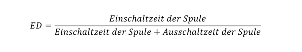
For SVS, all catalog values of the coils refer to a duty cycle of 100%.
A characteristic variable of a solenoid valve for specifying a flow rate value is the kv value. This value enables a manufacturer-independent comparison of solenoid valves with regard to the maximum flow rate. Based on the kv value, the flow rate can be determined by specifying the pressure drop from valve inlet to valve outlet, the density of the medium and the working pressure.
The kv value is determined experimentally according to the VDE 2173 standard, see the following figure. As a physical quantity, the kv value represents the amount of water in [m³/h] that flows through a solenoid valve at a pressure difference of 1 bar and a temperature in the range of 5°C and 40°C
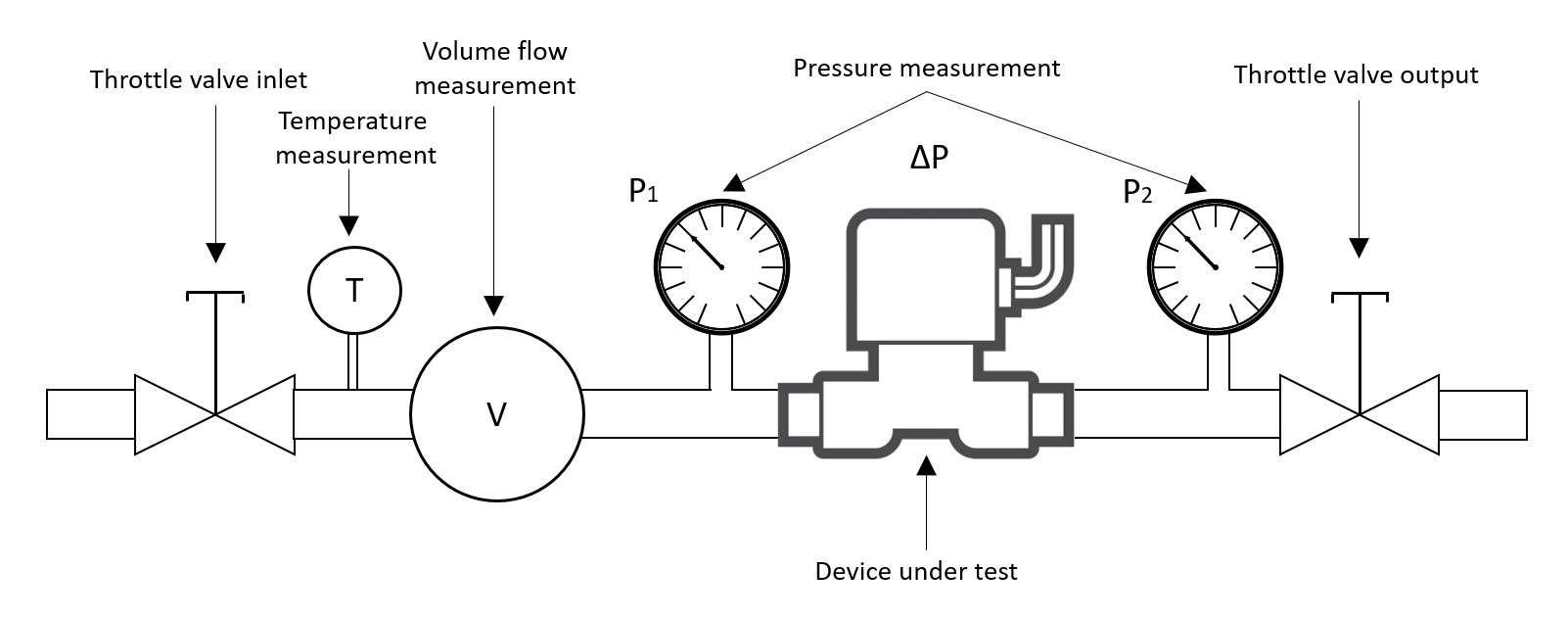
– Flow coefficient – kv – [m³/h]
– Flow rate – Q – [m³/h]
– Standard flow – Qn – [m³/h]
– Inlet pressure – p1 – [bar]
– Outlet pressure – p2 – [bar]
– Pressure difference – Δp – [bar]
– Temperature – T – [°C] bzw. [K]
DIN43650 valve connectors are durable valve connectors used in a wide range of industrial applications. As valve connectors, they represent the most widely used variant of the electrical connection of a solenoid valve. DIN 43650 valve connectors are available in three formats: form A, form B or form C. Depending on the coil size, form A is usually used for large coils and form B or C for small coils. Device connectors can be supplied as a pure connection element or also with integrated electronics.


Solenoid coils represent an inductive load for the voltage supply, whose current and voltage follow the following relationship: The voltage across the coil therefore depends on how fast the coil current changes. For AC coils, this results in the reactance XL of a coil. In switching operations with both alternating current and direct current, the result is that rapid changes in current caused by the solenoid coil being switched on or off lead to high voltages on the solenoid coil itself. These voltage peaks can destroy electronic components and thus cause damage to an electronic system. To prevent this, valve connectors are available with an integrated protective circuit. This protective circuit, in the form of a simple diode or a voltage-dependent resistor or TVS diode, smoothes out these voltage peaks and thus prevents damage to electronic components.
Valve connectors with and without protective circuit are available from SVS. For further information and available types, please refer to our product catalog or our website. We will also be happy to advise you on our device connectors.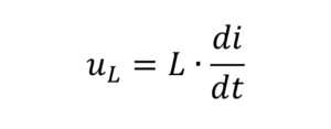
Die größte elektromagnetische Kraft z.B. bei NC-Ventilen ist erforderlich, um den Magnetkern entgegen der Druckkraft und der Kraft der Kernfeder anzuheben. Sobald der Magnetkern am Pol anliegt, ist lediglich die magnetische Kraft zur Kompensation der Kraft der Feder notwendig. Um den Energieverbrauch und die Erwärmung von Gleichstrom-Magnetspulen zu senken, sind Gerätestecker mit einer integrierten Leistungsreduktion erhältlich. Diese Gerätestecker versorgen die Magnetspule des Magnetventils in den ersten 600 Millisekunden mit der Nennspannung und vermindern dann den Effektivwert der Nennspannung auf ca. 60% durch eine Pulsweitenmodulation. Die herabgesenkte Spannung reicht aus, um den Kern angezogen zu halten und vermindert gleichzeitig die aufgenommene Leistung (auf ca. 40%) und dadurch die Erwärmung der Spule enorm.
Bei SVS sind Gerätestecker mit Leistungsreduktion für 12Vdc und 24Vdc verfügbar.
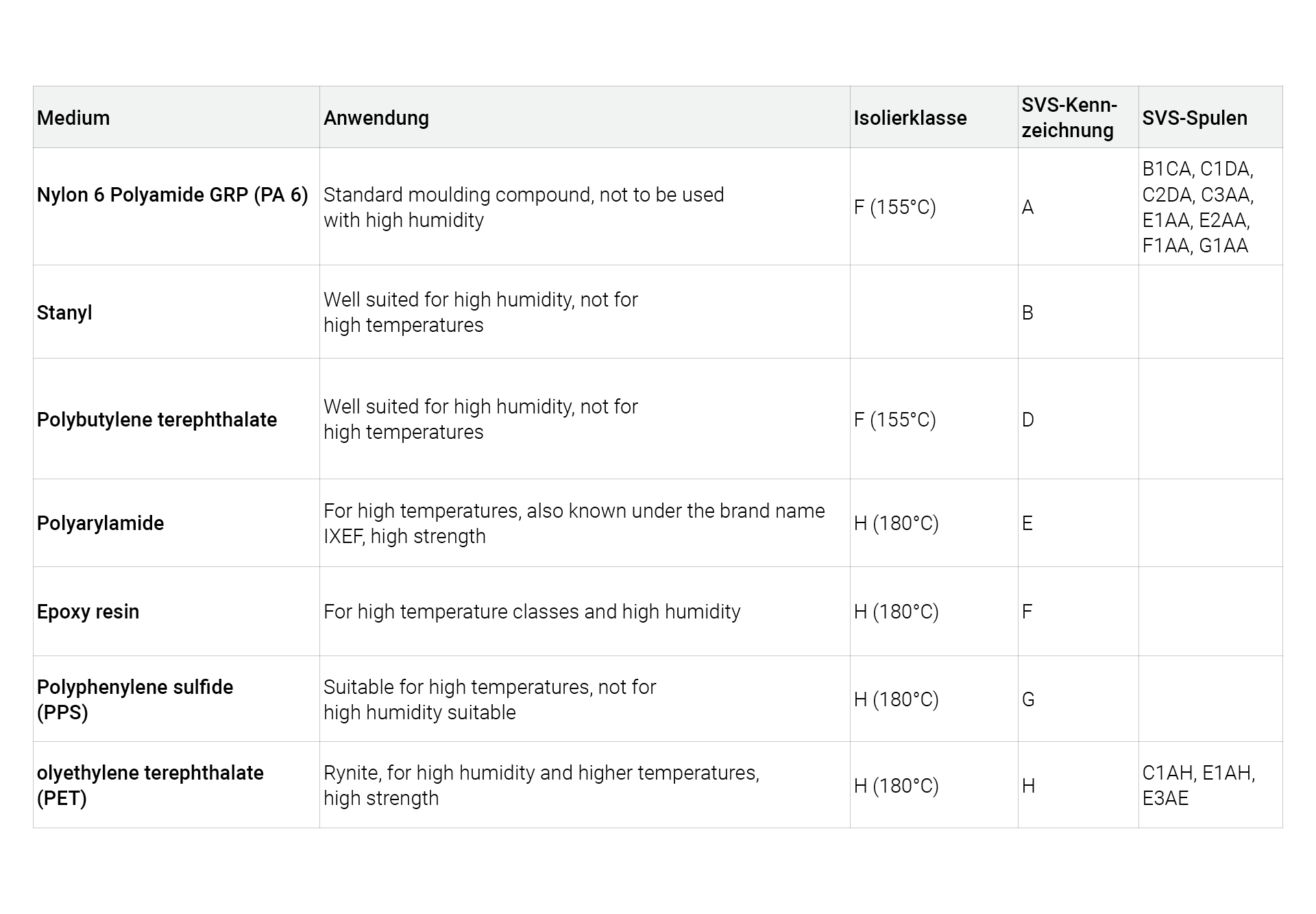
At SVS, solenoid coils are available for guide tube diameters of 7mm, 9mm, 13mm, 16mm and 19mm for DC and AC voltage. PA 6 and PET are used as moulding compounds. As the most common valve connection we offer our coils with plug according to DIN43650. Some types are also available with injected cables. For further information please refer to our product catalog or our website.
We will also be happy to advise you on our solenoid coils.
In general, solenoid valves with DC or AC coils can be used, allowing connection to a DC voltage or, for example, the AC mains. Constructively, a solenoid valve for AC voltage differs from a valve for DC voltage only by the short-circuit ring. This is not necessary for DC solenoid valves and is therefore often not present. The power calculation and the relationships between the electrical quantities of DC and AC coils are as follows:
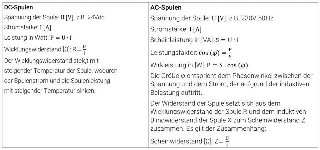
With alternating current, the current consumption is determined by the ohmic resistance of the coil wire and by the reactance of the coil. The latter is the product of the frequency of the voltage supply and the inductance of the magnet system. The inductance of the magnet system has a minimum when the core is not attracted and a maximum when the core is attracted. Accordingly, the inductance L is smaller when the core is not attracted than when it is attracted. Therefore, the current consumption is also larger when the core is not tightened, until the core is fully in contact with the pole. The power during tightening is called tightening power, which is greater than the so-called holding power.
For SVS, both the cold power and hot power of the DC solenoid coils, as well as the pickup and holding power of the AC solenoid coils are specified in the catalog.
In addition to the electrical power, the electromagnetic force of a coil is also indirectly influenced by its size. If two coils with identical electrical power but different sizes are compared, a much larger electromagnetic force can usually be generated with a larger coil. By having the same electrical power, both coils have the same ohmic resistance. With the larger coil, on the other hand, a thicker wire can be used and wound into a coil with a higher number of turns. The electromagnetic force for identical magnet systems is proportional to the square of the product of the coil current and the number of turns:

Solenoid valves are actuators used to control pressurized media. They are actuated by switching on the solenoid coil of the valve, whereupon the valve opens (Normally Closed, NC) or closes (Normally Open, NO). A solenoid valve closes when the so-called seat seal closes the valve seat. The solenoid valve can be actuated in three ways:
- Direct-operated
- Pilot operated (pilot controlled)
- Forced-acting (semi-direct-acting)
The four central elements of a solenoid valve are:
- the valve body, consisting of at least 2 ports (outlet and inlet) and a valve seat to close the valve.
- the guide tube to hold the solenoid coil and the solenoid core, which together with the pole in the guide tube close the magnetic circuit. In the case of AC voltage supplies, it is necessary for the pole to be equipped with a so-called short-circuit ring.
- the magnetic core, which is freely movable in the guide tube and serves to seal the valve seat or pilot bore.
- the coil, which generates an electromagnetic field by which the core is attracted to the pole.
The valve body – has 2 or 3 ports to make the connection to the rest of the pneumatic or hydraulic circuit. Depending on the application and medium, the valve body is usually made of plastic, brass, aluminum or stainless steel (colloquially and hereinafter referred to as stainless steel).
Guide tube, solenoid core and pole – are made entirely or partially of magnetizable stainless steels to create a magnetic circuit. The use and selection of the magnetic stainless steel influences the achievable electromagnetic force of the magnetic system and the corrosion resistance of the valve.
The valve seat – or its nozzle diameter (commonly referred to as nominal size) – influences the achievable flow rate of the valve. The larger the nominal size, the greater the achievable flow rate at a given pressure. Furthermore, the nominal size influences the switchable pressure of direct operated valves. The differential pressure from valve inlet to valve outlet multiplied by the area of the valve seat determines the force required to actuate the solenoid core, which the solenoid coil must apply to lift the solenoid core from the valve seat.
The seal – of the valve seat and the seals used in the valve determine with which media and at which temperatures the valve can be used. The hardness of the seat seal used also influences the abrasion resistance and the leakage rate.
The solenoid coil – serves as an energy converter from electrical energy to mechanical energy. The solenoid coil must be adapted to the existing electrical power supply (e.g. 230V 50Hz or 24Vdc) when designing the valve. The higher the power, i.e. the product of current through the coil and its number of turns, the higher the available mechanical force and thus the switchable pressure difference.
The short-circuit ring – is necessary when valves are operated on AC voltages. Due to the sinusoidal voltage supply, there are zeros both in the voltage curve and in the curve of the generated electromagnetic force of the solenoid system. To prevent the solenoid core from falling off at the zero points of the force curve, a short-circuit ring made of copper or silver is pressed into the solenoid pole. This prevents zeros of the electromagnetic force from occurring on the magnetic core and the latter from starting to oscillate, which causes a characteristic, loud 100 Hz hum.
The circuit diagram of a solenoid valve shows the type of actuation and reset of the valve as well as the switching positions that can be assumed. The following illustrations show this using a directly controlled 2/2-way NC solenoid valve.
In pilot-operated and positively controlled solenoid valves, the seat seal is no longer actuated purely by the electromagnetic force, but also by the force from the pressure difference between the inlet pressure and the outlet pressure. For pilot-operated or force-operated valves, the switching symbol is therefore adapted to indicate this.
The valve body of 2/2-way solenoid valves has an inlet and an outlet which are connected to each other via a valve seat. Depending on the design, the solenoid valve assumes the position “Normally Closed” (NC) or “Normally Open” (NO) in the non-activated state. An NC solenoid valve locks the valve seat when the solenoid is not energized, preventing flow from inlet to outlet. When the solenoid is energized, the seat seal opens the valve seat and flow is possible from the inlet to the outlet. In a NO solenoid valve, a medium can flow from the inlet to the outlet when the solenoid coil is in the non-actuated state. If the solenoid coil is switched on, the seat seal blocks the valve seat and flow from the inlet to the outlet is interrupted.
For SVS, the identification for an NC or an NO valve is made on the basis of the third digit or the first letter in the product key. The letter A stands for the NC function, the letter B for the NO function. This means, for example, for a valve type 15 NO: 15B-1B20FZ-AC2DA 23050
2/2-way solenoid valves - direct operated
In a direct operated valve, the armature with the seat seal is actuated purely by the electromagnetic force of the solenoid coil. The rule for NC valves is that the higher the pressure and the larger the nominal size of the valve, the more force is required to actuate the solenoid core. In NO valves, the electromagnetic force works against the spring force of the spring, which pushes the seal carrier of the seat seal away from the valve seat. In order to close the valve, the electromagnetically generated force must therefore be greater than the spring force. The maximum pressure at which the valve still opens is determined by the spring.
At SVS, type series 12, 15, 20, 21, 27 made of brass and type series 31, 32, 34, 35 and 37 made of stainless steel are available as direct operated 2/2-way solenoid valves.
Due to the high demand for electromagnetic force, directly controlled solenoid valves are not suitable for switching large nominal sizes and/or large pressure differences. To reduce the required electromagnetic force and to be able to use smaller and thus more energy-saving solenoid coils, pilot operated solenoid valves are used.
n these valves, the main sealing element in the form of a diaphragm or piston closes the main seat of the valve by the medium filling the space above through a small hole in the diaphragm or laterally around the piston, and by the pressure on the diaphragm or piston these close the valve seat. The space above the diaphragm or piston can be relieved via a smaller, direct-acting solenoid valve in NC or NO design, the so-called pilot valve, which lifts them off the main seat and allows flow through the valve. With this principle, a corresponding minimum pressure of the medium is necessary to lift the diaphragm or piston from the valve seat. The function of the pilot valve (NO or NC) determines whether the entire valve is normally closed or normally open. The advantage of pilot operated valves is the possibility to switch high pressures at large nominal sizes with relatively small and low-power solenoid coils.
At SVS, type series 50, 51 made of brass and type series 60, 62 and 63 made of stainless steel are available as pilot operated 2/2-way solenoid valves. The valve type 63 is a high pressure version with switchable pressures up to 100 bar.
To enable application with no or almost no pressure difference, positively controlled valves are used. In this type of valve, the pilot valve sits centrally above the main sealing element in the form of a diaphragm or piston, which in turn closes the valve seat. The solenoid core of the pilot valve closes a nozzle in the center of the main sealing element. In addition, the magnetic core and the main sealing element are coupled to each other either by a spring or rigidly, depending on the design. To fill the space above the main seal with the medium, there is a small hole in the diaphragm or a small flow around the piston is possible. As with pilot-operated valves, the pilot valve can be designed as an NO or NC valve. If the solenoid armature now lifts from the nozzle in the main seal, the pressure above the main seal element is relieved and the solenoid core lifts together with the main seal. For NC valves and low pressures, the electromagnetic force lifts the solenoid core together with the main seal, which is why the valve behaves like a direct-acting valve. At higher pressure differentials, the force of the solenoid is no longer sufficient to open the main seal as well. In this case, the valve acts like a pilot-operated valve in which the space above the main seal is relieved by the pilot valve and the diaphragm or the piston is lifted from the valve seat by the pressure difference.
At SVS, type series 70 made of brass and type series 76 made of stainless steel are available as positively controlled 2/2-way solenoid valves.
For SVS, all catalog values of the coils refer to a duty cycle of 100%.A characteristic variable of a solenoid valve for specifying a flow rate value is the kv value. This value enables a manufacturer-independent comparison of solenoid valves with regard to the maximum flow rate. Based on the kv value, the flow rate can be determined by specifying the pressure drop from valve inlet to valve outlet, the density of the medium and the working pressure.
The kv value is determined experimentally according to the VDE 2173 standard, see the following figure. As a physical quantity, the kv value represents the amount of water in [m³/h] that flows through a solenoid valve at a pressure difference of 1 bar and a temperature in the range of 5°C and 40°C
– Flow coefficient – kv – [m³/h]
– Flow rate – Q – [m³/h]
– Standard flow – Qn – [m³/h]
– Inlet pressure – p1 – [bar]
– Outlet pressure – p2 – [bar]
– Pressure difference – Δp – [bar]
– Temperature – T – [°C] bzw. [K]
At SVS, solenoid coils are available for guide tube diameters of 7mm, 9mm, 13mm, 16mm and 19mm for DC and AC voltage. PA 6 and PET are used as moulding compounds. As the most common valve connection we offer our coils with plug according to DIN43650. Some types are also available with injected cables. For further information please refer to our product catalog or our website.
We will also be happy to advise you on our solenoid coils.
With alternating current, the current consumption is determined by the ohmic resistance of the coil wire and by the reactance of the coil. The latter is the product of the frequency of the voltage supply and the inductance of the magnet system. The inductance of the magnet system has a minimum when the core is not attracted and a maximum when the core is attracted. Accordingly, the inductance L is smaller when the core is not attracted than when it is attracted. Therefore, the current consumption is also larger when the core is not tightened, until the core is fully in contact with the pole. The power during tightening is called tightening power, which is greater than the so-called holding power.
For SVS, both the cold power and hot power of the DC solenoid coils, as well as the pickup and holding power of the AC solenoid coils are specified in the catalog.