Solenoid valves are actuators used to control pressurized media. They are actuated by switching on the solenoid coil of the valve, whereupon the valve opens (Normally Closed, NC) or closes (Normally Open, NO). A solenoid valve closes when the so-called seat seal closes the valve seat. The solenoid valve can be actuated in three ways:
- Direct operated
- Pilot operated (pilot controlled)
- Forced-acting (semi-direct-acting)
The four central elements of a solenoid valve are:
- the valve body, consisting of at least 2 ports (outlet and inlet) and a valve seat to close the valve.
- the guide tube to hold the solenoid coil and the solenoid core, which together with the pole in the guide tube close the magnetic circuit. In the case of AC voltage supplies, it is necessary for the pole to be equipped with a so-called short-circuit ring.
- the magnetic core, which is freely movable in the guide tube and serves to seal the valve seat or pilot bore.
- the coil, which generates an electromagnetic field by which the core is attracted to the pole.

The circuit diagram of a solenoid valve shows the type of actuation and reset of the valve as well as the switching positions that can be assumed. The following illustrations show this using a directly controlled 2/2-way NC solenoid valve.

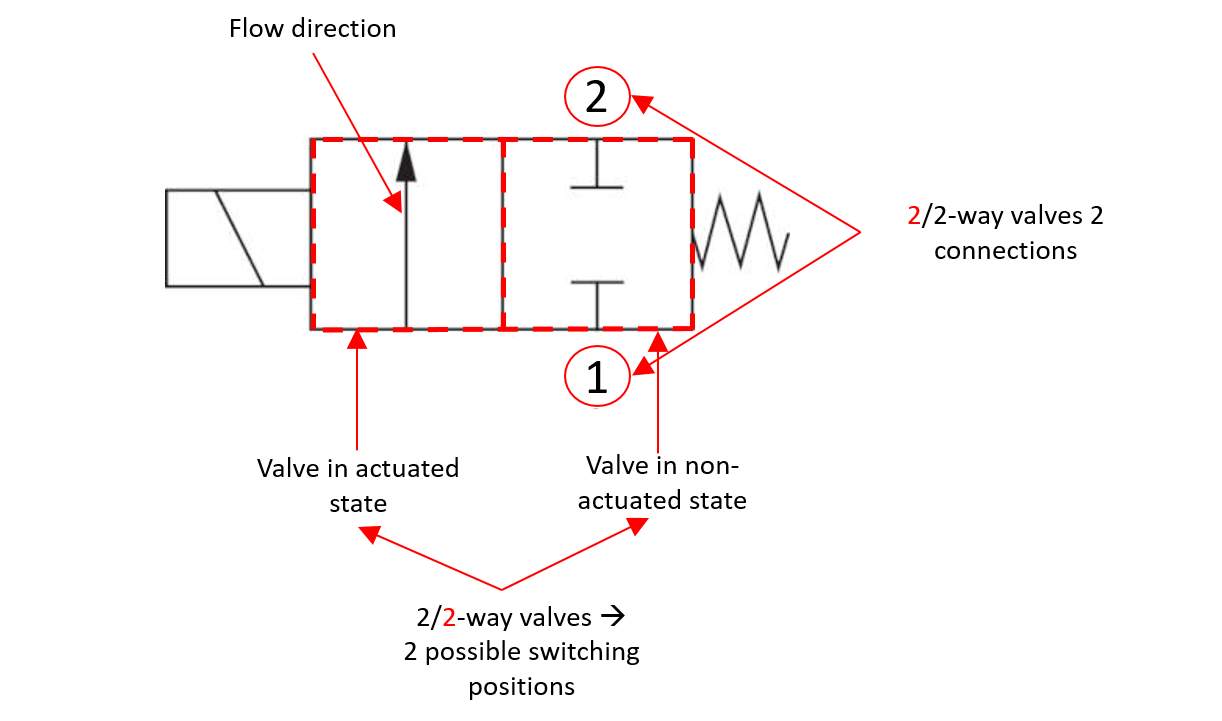 In pilot-operated and positively controlled solenoid valves, the seat seal is no longer actuated purely by the electromagnetic force, but also by the force from the pressure difference between the inlet pressure and the outlet pressure. For pilot-operated or force-operated valves, the switching symbol is therefore adapted to indicate this.

For SVS, the identification for an NC or an NO valve is made on the basis of the third digit or the first letter in the product key. The letter A stands for the NC function, the letter B for the NO function. This means, for example, for a valve type 15 NO: 15B-1B20FZ-AC2DA 23050
In a direct operated valve, the armature with the seat seal is actuated purely by the electromagnetic force of the solenoid coil. The rule for NC valves is that the higher the pressure and the larger the nominal size of the valve, the more force is required to actuate the solenoid core. In NO valves, the electromagnetic force works against the spring force of the spring, which pushes the seal carrier of the seat seal away from the valve seat. In order to close the valve, the electromagnetically generated force must therefore be greater than the spring force. The maximum pressure at which the valve still opens is determined by the spring.

At SVS, type series 12, 15, 20, 21, 27 made of brass and type series 31, 32, 34, 35 and 37 made of stainless steel are available as direct operated 2/2-way solenoid valves.

At SVS, type series 50, 51 made of brass and type series 60, 62 and 63 made of stainless steel are available as pilot operated 2/2-way solenoid valves. The valve type 63 is a high pressure version with switchable pressures up to 100 bar.
To enable application with no or almost no pressure difference, positively controlled valves are used. In this type of valve, the pilot valve sits centrally above the main sealing element in the form of a diaphragm or piston, which in turn closes the valve seat. The solenoid core of the pilot valve closes a nozzle in the center of the main sealing element. In addition, the magnetic core and the main sealing element are coupled to each other either by a spring or rigidly, depending on the design. To fill the space above the main seal with the medium, there is a small hole in the diaphragm or a small flow around the piston is possible. As with pilot-operated valves, the pilot valve can be designed as an NO or NC valve. If the solenoid armature now lifts from the nozzle in the main seal, the pressure above the main seal element is relieved and the solenoid core lifts together with the main seal. For NC valves and low pressures, the electromagnetic force lifts the solenoid core together with the main seal, which is why the valve behaves like a direct-acting valve. At higher pressure differentials, the force of the solenoid is no longer sufficient to open the main seal as well. In this case, the valve acts like a pilot-operated valve in which the space above the main seal is relieved by the pilot valve and the diaphragm or the piston is lifted from the valve seat by the pressure difference.

At SVS, type series 70 made of brass and type series 76 made of stainless steel are available as positively controlled 2/2-way solenoid valves.
Der Ventilkörper von 2/2-Wege-Magnetventilen hat einen Eingang und einen Ausgang die über einen Ventilsitz miteinander verbunden sind. Je nach Ausführung nimmt das Magnetventil im nicht aktivierten Zustand die Stellung „normal geschlossen“ (Normally Closed, NC) oder „normal offen“ (Normally Open, NO) ein.
Ein NC-Magnetventil sperrt den Ventilsitz im nicht betätigten Zustand der Magnetspule wodurch kein Durchfluss von Eingang zu Ausgang möglich ist. Wird die Magnetspule eingeschaltet, öffnet die Sitzdichtung den Ventilsitz und ein Durchfluss vom Eingang zum Ausgang ist möglich.
Bei einem NO-Magnetventil kann ein Medium im nicht betätigten Zustand der Magnetspule vom Eingang zum Ausgang strömen. Wird die Magnetspule eingeschalten, versperrt die Sitzdichtung den Ventilsitz und der Durchfluss von Eingang zu Ausgang ist unterbrochen.
Bei SVS erfolgt die Kennzeichnung für ein NC- oder ein NO-Ventil anhand der dritten Stelle bzw. des ersten Buchstabens im Produktschlüssel. Der Buchstabe A steht für die NC-Funktion, der Buchstabe B für die NO-Funktion. Daraus folgt z.B. für ein Ventil Typ 15 NO: 15B-1B20FZ-AC2DA 23050
Bei einem direktgesteuerten Ventil wird der Anker mit der Sitzdichtung rein durch die elektromagnetische Kraft der Magnetspule betätigt. Dabei gilt bei NC-Ventilen, dass je höher der Druck und je größer die Nennweite des Ventils ist, umso mehr Kraft wird benötigt, um den Magnetkern zu betätigen. Bei NO-Ventilen arbeitet die elektromagnetische Kraft gegen die Federkraft der Feder, welche den Dichtungsträger der Sitzdichtung von dem Ventilsitz wegdrückt. Um das Ventil schließen zu können, muss die elektromagnetisch erzeugte Kraft somit größer als die Federkraft sein. Der Maximaldruck, bei dem das Ventil noch öffnet, wird von der Feder bestimmt.
Bei SVS sind die Typenreihen 12, 15, 20, 21, 27 aus Messing und die Typenreihen 31, 32, 34, 35 und 37 aus Edelstahl als direktgesteuerte 2/2-Wege-Magnetventile verfügbar.
Aufgrund des hohen Bedarfs an elektromagnetischer Kraft eignen sich direktgesteuerte Magnetventile nicht um große Nennweiten und/oder große Druckdifferenzen zu schalten. Um die notwendige elektromagnetische Kraft zu senken und kleinere und somit energiesparendere Magnetspulen einsetzen zu können, werden vorgesteuerte Magnetventile eingesetzt.
Bei SVS sind die Typenreihen 50, 51 aus Messing und die Typenreihen 60, 62 und 63 aus Edelstahl als vorgesteuerte 2/2-Wege-Magnetventile verfügbar. Der Ventiltyp 63 ist eine Hochdruckausführung mit schaltbaren Drücken bis 100 bar.
Um eine Anwendung bei keiner oder fast keiner Druckdifferenz zu ermöglichen, werden zwangsgesteuerte Ventile eingesetzt. Bei dieser Ventilart sitzt das Pilotventil zentral über dem Hauptdichtungselement in Form einer Membrane oder einem Kolben, welches wiederum den Ventilsitz verschließt. Der Magnetkern des Pilotventils verschließt dabei eine Düse in der Mitte des Hauptdichtungselements. Zusätzlich sind der Magnetkern und das Hauptdichtungselement je nach Ausführung mit einer Feder oder starr miteinander gekoppelt. Um den Raum oberhalb der Hauptdichtung mit dem Medium zu füllen, befindet sich eine kleine Bohrung in der Membrane bzw. ist ein geringes Umströmen des Kolbens möglich. Wie bei vorgesteuerten Ventile kann das Pilotventil als NO- oder NC-Ventil ausgeführt sein. Hebt nun der Magnetanker von der Düse in der Hauptdichtung ab, wird der Druck oberhalb des Hauptdichtungselements abgebaut und der Magnetkern hebt sich gemeinsam mit der Hauptdichtung. Bei NC-Ventilen und niedrigen Drücken wird durch die elektromagnetische Kraft der Magnetkern gemeinsam mit der Hauptdichtung angehoben, weshalb sich das Ventil wie ein direktgesteuertes Ventil verhält. Bei höheren Druckdifferenzen reicht die Kraft des Elektromagneten nicht mehr aus, um die Hauptdichtung ebenfalls noch zu öffnen. Hier agiert das Ventil wie ein vorgesteuertes Ventil bei dem der Raum oberhalb der Hauptdichtung durch das Pilotventil entlastet wird und die Membrane oder der Kolben durch die Druckdifferenz vom Ventilsitz abheben.
Bei SVS ist die Typenreihe 70 aus Messing und die Typenreihe 76 aus Edelstahl als zwangsgesteuertes 2/2-Wege-Magnetventil verfügbar.

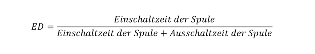
The specification of the duty cycle primarily concerns the solenoid coil of a solenoid valve. Coils of ordinary solenoid valves are usually designed for a duty cycle of 100%. Non-continuous operation of solenoid coils allows the coil to be used under more demanding conditions, such as a higher voltage or an increased maximum ambient temperature. In any case, the use of a coil under such conditions requires consultation with the coil manufacturer. As a general rule, continuous operation exists for duty cycles of 15 minutes or more. The duty cycle is calculated according to the following formula:
 For SVS, all catalog values of the coils refer to a duty cycle of 100%.
DIN43650 valve connectors are durable valve connectors used in a wide range of industrial applications. As valve connectors, they represent the most widely used variant of the electrical connection of a solenoid valve. DIN 43650 valve connectors are available in three formats: form A, form B or form C. Depending on the coil size, form A is usually used for large coils and form B or C for small coils. Device connectors can be supplied as a pure connection element or also with integrated electronics.


Solenoid coils represent an inductive load for the voltage supply, whose current and voltage follow the following relationship:

The greatest electromagnetic force, e.g. in NC valves, is required to lift the magnetic core against the pressure force and the force of the core spring. As soon as the solenoid core is in contact with the pole, only the magnetic force is necessary to compensate the force of the spring. To reduce the power consumption and heating of DC solenoid coils, device plugs with an integrated power reduction are available. These device plugs supply the solenoid coil of the solenoid valve with the nominal voltage for the first 600 milliseconds and then reduce the effective value of the nominal voltage to approx. 60% by means of pulse width modulation. The lowered voltage is sufficient to keep the core attracted and at the same time reduces the absorbed power (to approx. 40%) and thus the heating of the coil enormously.
Device connectors with power reduction for 12Vdc and 24Vdc are available from SVS.

At SVS, solenoid coils are available for guide tube diameters of 7mm, 9mm, 13mm, 16mm and 19mm for DC and AC voltage. PA 6 and PET are used as moulding compounds. As the most common valve connection we offer our coils with plug according to DIN43650. Some types are also available with injected cables. For further information please refer to our product catalog or our website.
In general, solenoid valves with DC or AC coils can be used, allowing connection to a DC voltage or, for example, the AC mains. Constructively, a solenoid valve for AC voltage differs from a valve for DC voltage only by the short-circuit ring. This is not necessary for DC solenoid valves and is therefore often not present. The power calculation and the relationships between the electrical quantities of DC and AC coils are as follows:
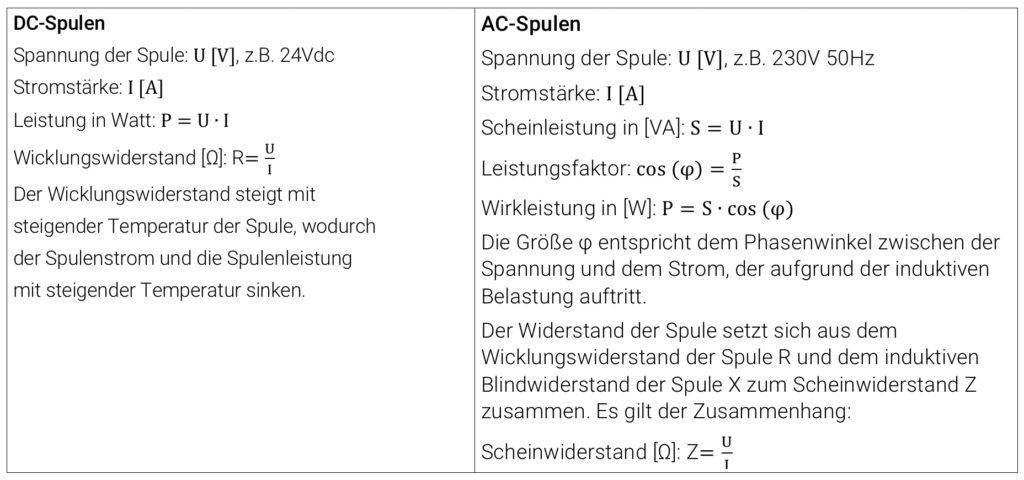
With alternating current, the current consumption is determined by the ohmic resistance of the coil wire and by the reactance of the coil. The latter is the product of the frequency of the voltage supply and the inductance of the magnet system. The inductance of the magnet system has a minimum when the core is not attracted and a maximum when the core is attracted. Accordingly, the inductance L is smaller when the core is not attracted than when it is attracted. Therefore, the current consumption is also larger when the core is not tightened, until the core is fully in contact with the pole. The power during tightening is called tightening power, which is greater than the so-called holding power.
In addition to the electrical power, the electromagnetic force of a coil is also indirectly influenced by its size. If two coils with identical electrical power but different sizes are compared, a much larger electromagnetic force can usually be generated with a larger coil. By having the same electrical power, both coils have the same ohmic resistance. With the larger coil, on the other hand, a thicker wire can be used and wound into a coil with a higher number of turns. The electromagnetic force for identical magnet systems is proportional to the square of the product of the coil current and the number of turns:

